← All projects

Fluid Structure Interaction of a Formula One Front Wing

FSI STAR-CCM+ CFD Aeroelasticity Transient Simulation

This project demonstrates how the transient aeroelastic behaviour of a front wing can influence its aerodynamic characteristics.

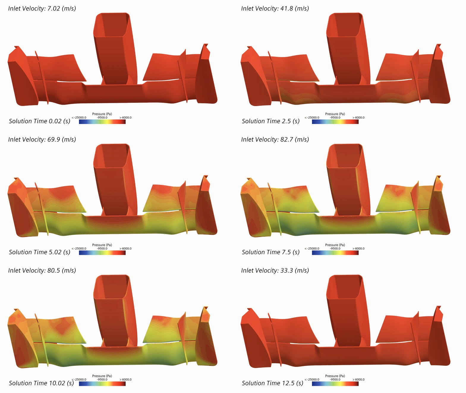
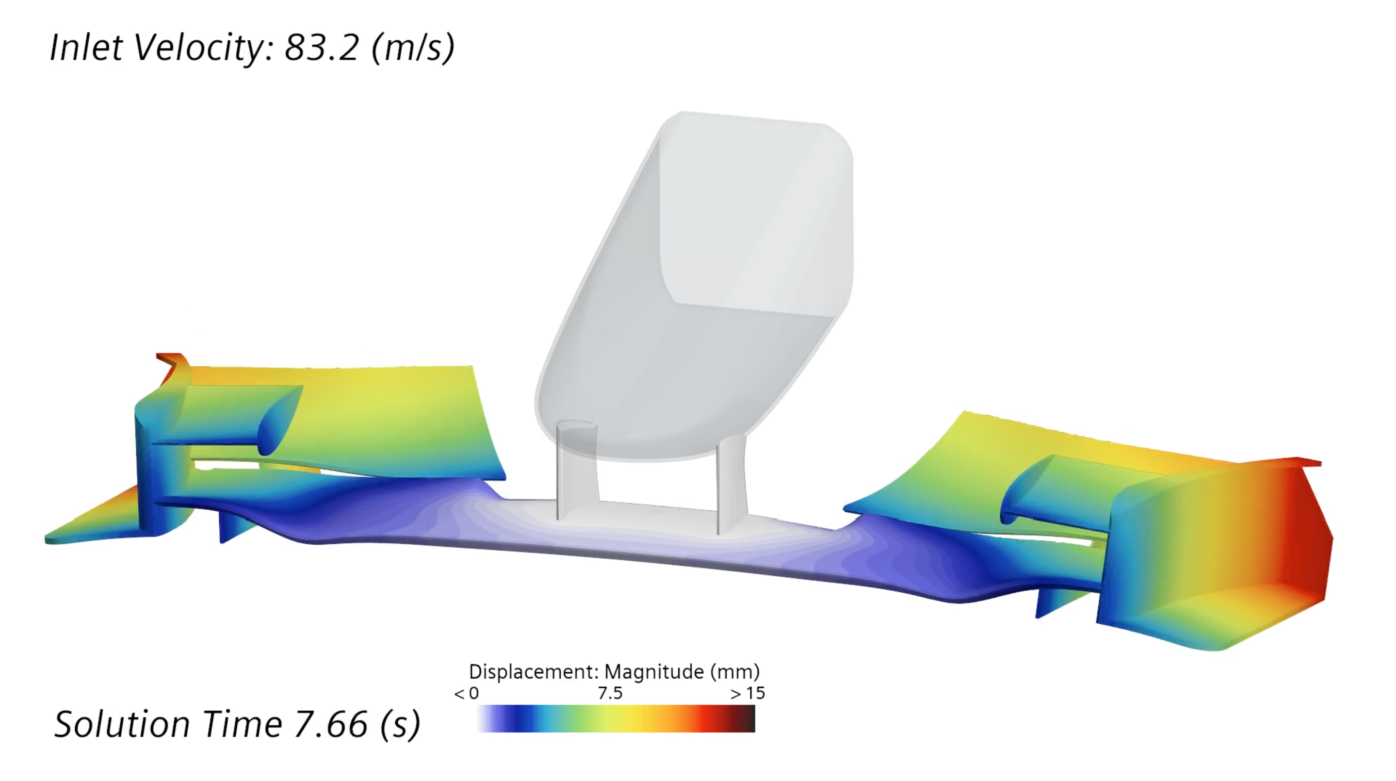
CFD visualization of a Formula 1 front wing under aerodynamic load

Overview

My theory is that front wings are deliberately made flexible to reduce lift-induced drag at high speeds, and increase grip at the front on lower speed corners for faster turn-in.

The aim of this project was to investigate how aeroelastic behaviour affects loading of a front wing during an acceleration and deceleration cycle.

Representative orthotropic properties were adopted for an equivalent CFRP laminate, with directional stiffness selected to approximate the behaviour of a high-performance composite wing structure.

Methodology

The simplified structural material model and isolated aerodynamic geometry mean the results are intended to demonstrate aeroelastic behaviour and FSI methodology rather than predict the deformation of a specific physical Formula 1 front wing.

The following assumptions were therefore adopted:

  • Incompressible flow,
  • k–ω SST RANS turbulence model,
  • Linear elastic structural behaviour,
  • Isolated front wing geometry,
  • Moving ground plane.

Two-way coupling was used, allowing structural deformation to modify the fluid domain and subsequent aerodynamic loading.

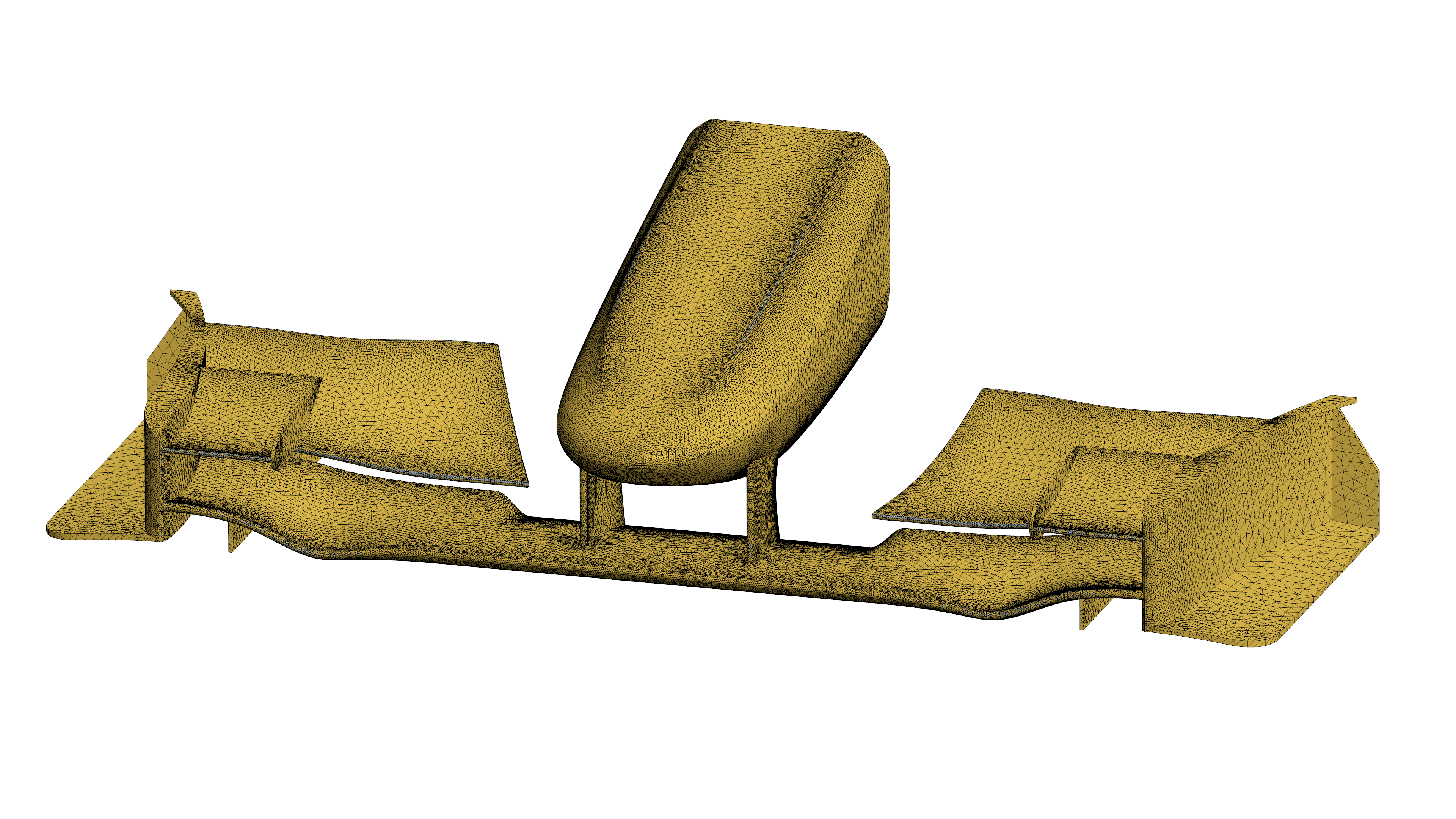
Tetrahedral fluid domain mesh highlighting refinement regions

Simulation Setup

Tetrahedral meshes were generated across both the fluid and solid domains to facilitate consistent node-to-face mapping at the decoupled fluid-structure interfaces.

Targeted surface and volumetric controls refined the fluid mesh in critical high-gradient regions, notably along the leading and trailing edges, flap slot gaps, and endplate vortex shedding paths.

Domain and mesh sensitivity studies were conducted to ensure solution independence from spatial resolution and boundary blockage effects.

Structurally, the nosecone mounting interface was constrained with fixed boundary conditions, while all aerodynamic surfaces remained unconstrained to capture dynamic elastic deflection.
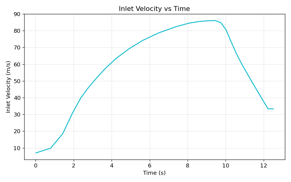
Graph showing the dynamic acceleration profile of inlet velocity versus time

Transient Loading

Transient aerodynamic loading was derived from telemetry of Kimi Antonelli’s 2026 Silverstone pole lap, reconstructing the dynamic acceleration profile along the Hangar Straight.

The extracted velocity trace was formatted and mapped into STAR-CCM+ via a time-dependent CSV table to drive both the inlet boundary condition and the moving ground plane.
Velocity streamlines illustrating the initial domain settling period

Flow Preconditioning

Unconditioned startup transients are demonstrated here, illustrating the initial domain settling period.

To eliminate startup initialisation artefacts from the aeroelastic data, the final methodology incorporated a 3.0-second initialisation period (corresponding to three domain flow-through times) to establish a statistically steady flow field before dynamic coupling.
Results & Reflections

Animation demonstrating the structural displacement of the front wing

Aeroelastic Response

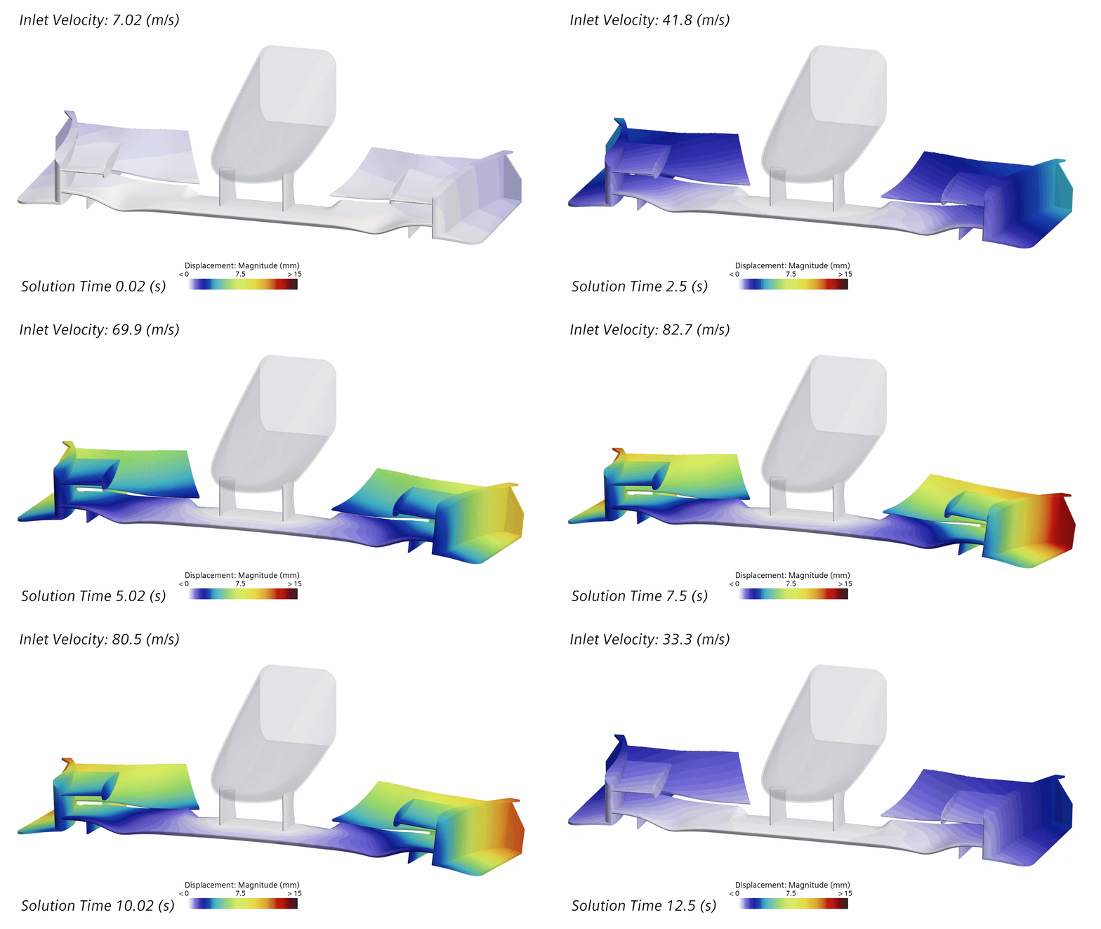
As dynamic pressure increases, the outboard wing elements visibly deflect and twist, effectively reducing the local angle of attack. This animation uses a vector warp to exaggerate the deformation by a factor of 10, clearly highlighting the aeroelastic washout that drives the load-shedding behaviour.

Graph plotting wing tip displacement components and magnitude versus time

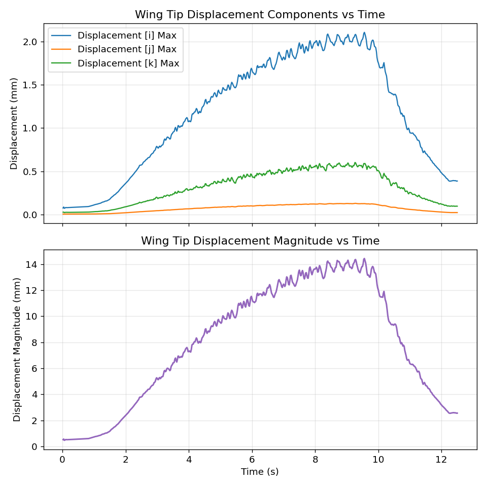
Wing tip displacement closely tracks the velocity ramp, scaling predictably with dynamic pressure (∝ V²).

  • Peak Loading: Displacement rises to ~14.4 mm as inlet velocity peaks at 86 m/s, with a slight lag during deceleration due to structural inertia.
  • Dynamic Excitation: High-frequency oscillations riding on the main trend suggest that unsteady aerodynamic loads are exciting a structural mode.
  • Measurement Note: The reported peak magnitude represents the absolute maximum displacement across the entire wing, rather than a single co-located probe, explaining why it differs from the vector sum of the individual directional axes.
Pressure contour animation on the suction surface of the wing elements

This pressure animation reveals the aerodynamic mechanism driving the wing vibration. Unsteady flow structures on the suction surface of the second element induce oscillating aerodynamic loads, which directly cause the observed structural displacement.

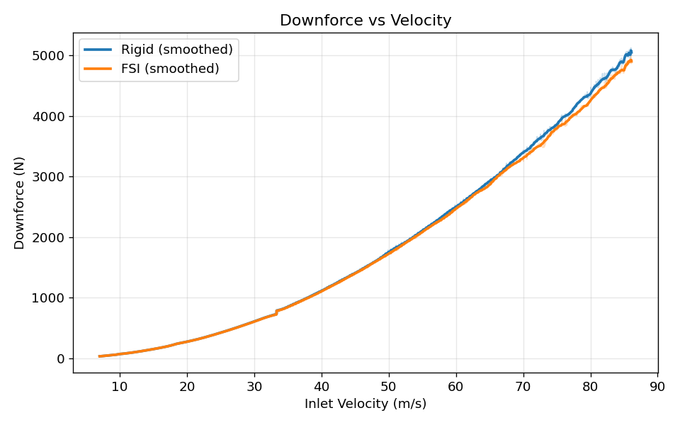
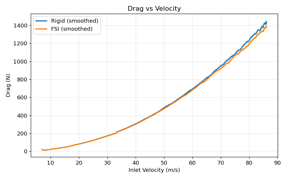
Graph comparing downforce generation between rigid and deformable wings Graph comparing drag generation between rigid and deformable wings

Rigid vs Deformable Comparison

An identical transient simulation was conducted with a non-deforming mesh to test the extents of the aeroelastic effect.

The FSI results directly support the initial hypothesis, demonstrating how aeroelasticity acts as a passive aerodynamic optimisation system. At lower velocities, the deformable wing predictions closely align with the rigid baseline. This indicates that the wing retains its structural stiffness at low speeds, preserving essential downforce and front-end grip for faster turn-in.

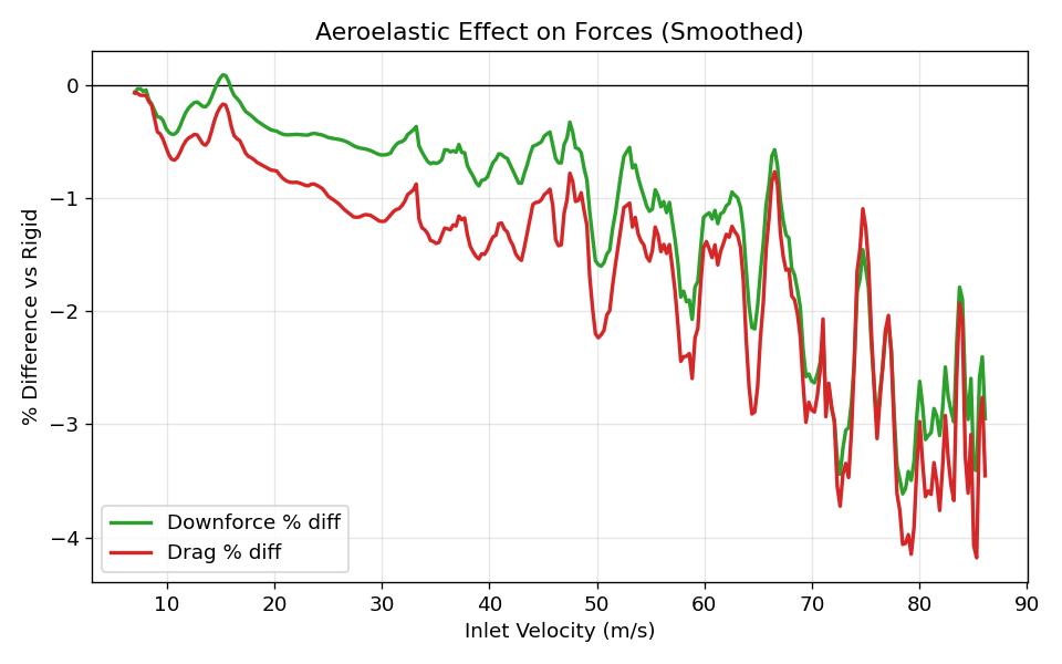
Graph showing the percentage difference in forces due to the aeroelastic effect

As velocity increases down the straight, dynamic pressure forces the wing to deflect. At the maximum simulated velocities, this aeroelastic "washout" sheds approximately 2-4% of downforce and 2-3% of drag relative to a rigid structure. Shedding downforce at high speeds is a highly beneficial trade-off to simultaneously shed lift-induced drag, ultimately increasing top speed without compromising low-speed cornering performance.